THE PROCESS
HARDWARE AND TOOLS USED
- Autodesk Eagle - CNC Milling machine - Arduino - Various electronic components listed below
1ST PROTOTYPE
For this week assignment I decided to make a light sensor that I can interface later on with processing . First I started by surfing the net to find some examples and tutorials that are close to what I was looking for but I could not find something that matches the idea in my head so for this reason I preferred to start with smoothing that is very simple and basic and later on I can build on it .
To kick of the project I followed the same strategy that I followed in the input devices week which is first to prepare a prototype before moving to the milling process. However, I decided to follow a simple Attiny85 tutorial that I found online, Below is the link for your reference :
+ Attiny 85 light sensor HERE.
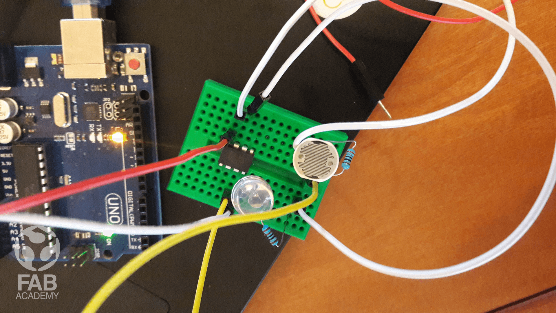
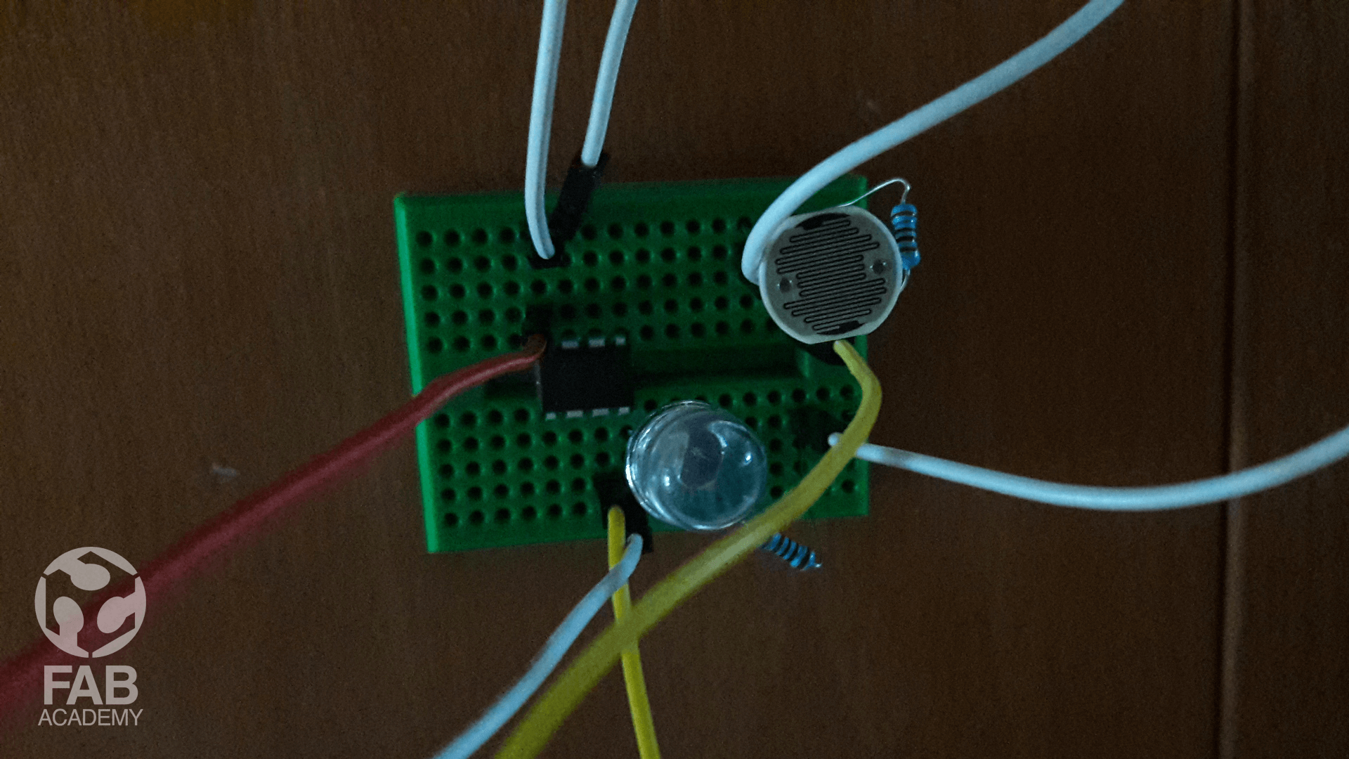
Then after getting all the necessary components from a local Electronic store I followed exactly the same steps as mentioned in the tutorial . For executing this tutorial I used a mini breadboard in order to speed up the process and I used Arduino UNO as ISP programmer .
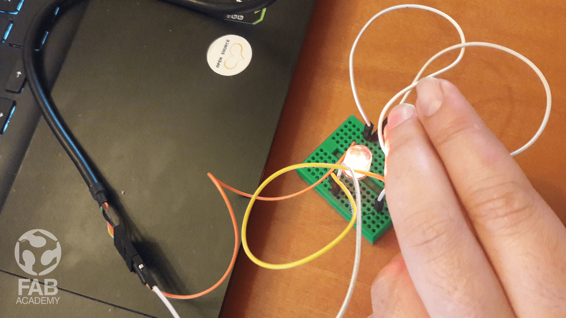
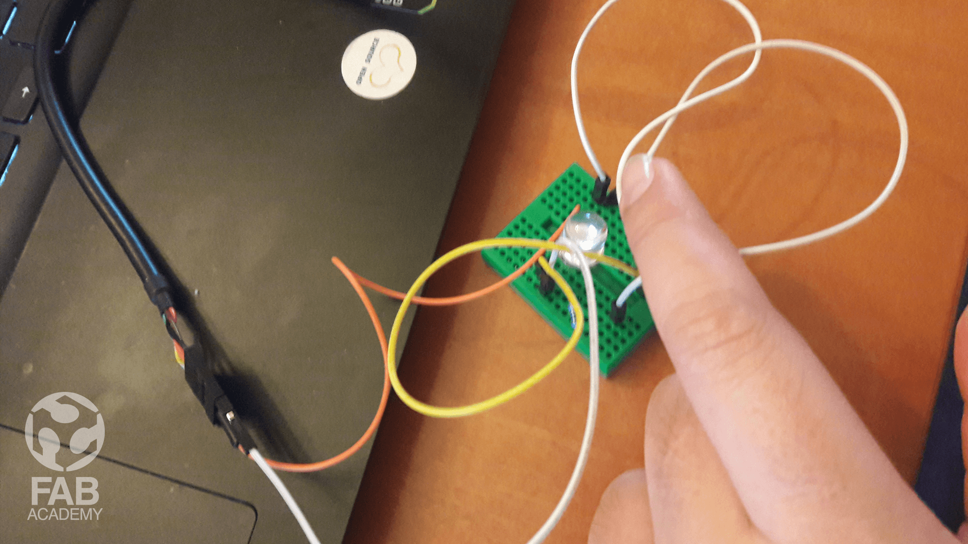
However after wiring all the pins correctly to Arduino board and unloading the code I started to see the led light blinking and interacting with the light sensor. I was really happy to see my first prototype is working especially it was my first time to program a microcontroller that is directly plugged in a breadboard and this made me super confident to move on and apply the same schematic on a PSB board .
PCB DESIGN AND PRODUCTION
A few days before going to echofab to start milling a professional looking PCB for this week assignment I knew about h06 Bluetooth module and after reading many tutorials and documentations online on how to connect h06 Bluetooth module to Arduino and microcontrollers I decided to use it so I can interface the led light with processing later on this way I can combine 3 different assignments in one assignment and this microcontroller might be useful for my final project.
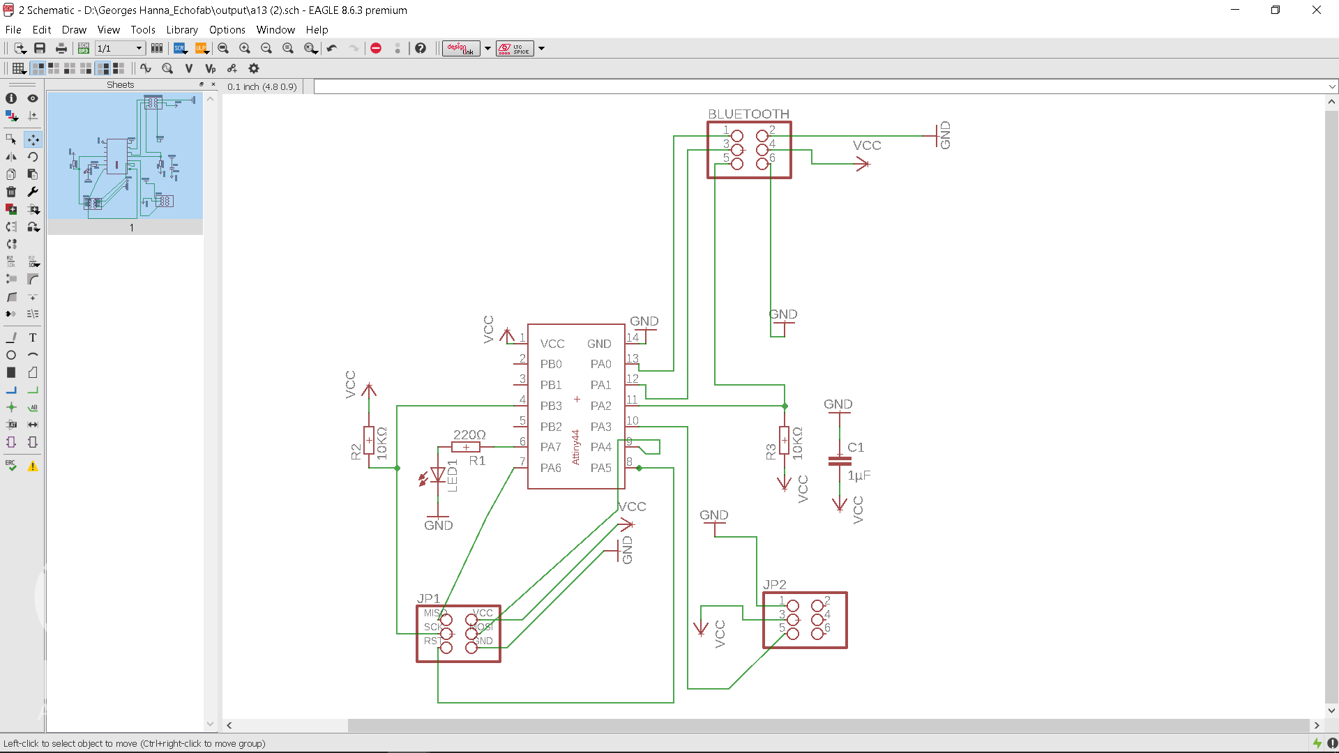
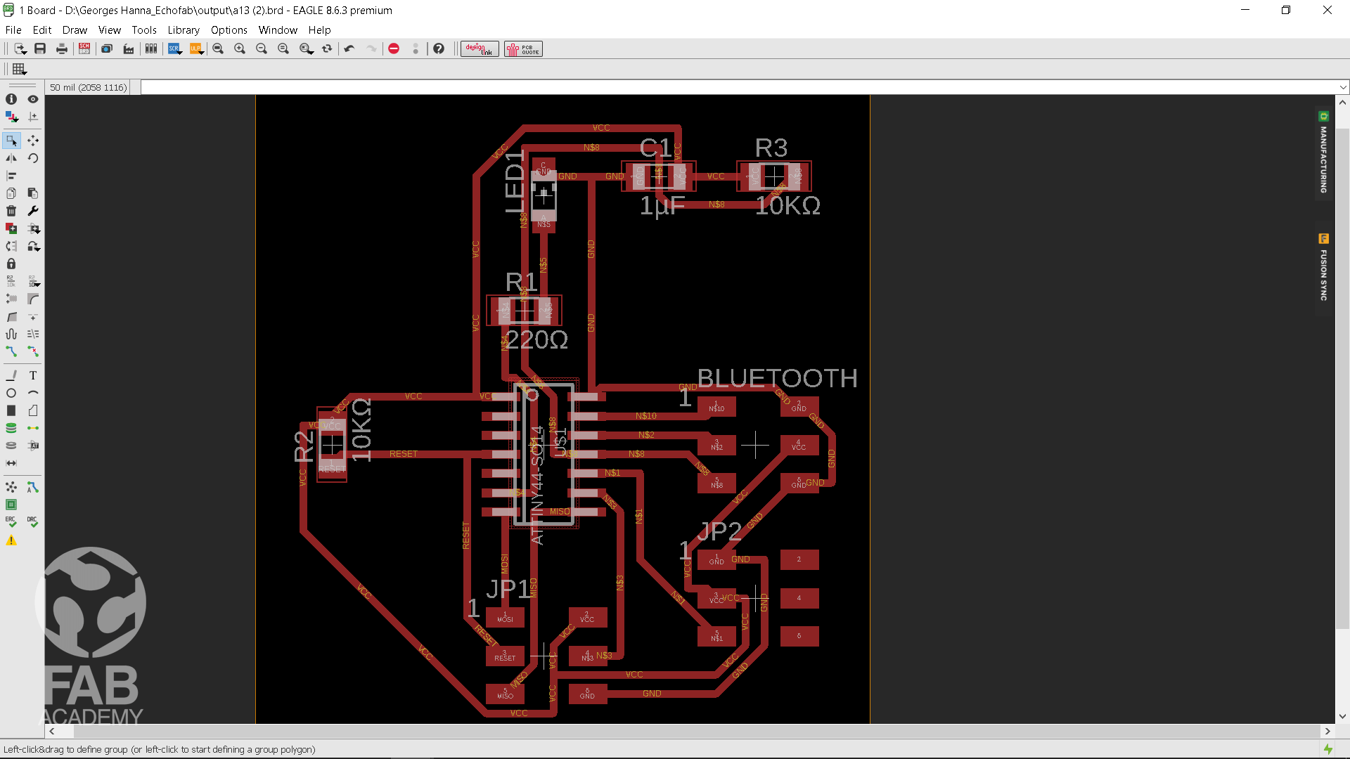
To begin with, I took the first prototype I did as a reference point to start and I began with designing the schematic as shown in image #06 and after that when I was done with the schematic design I moved to the board design as shown in image #07 for that process I used eagle and I reason decided to use Attiny 44 SMD microcontroller instead of Attiny 85 since it has more pins which gives me total freedom to attach more electronic components and the Attiny44 were available at our lab
Below is a list of the parts I used :
+ ATtiny 44
+ Non SMD photo resistor
+ 200Ω Resistor - Protects the LED from too much current.
+ 10kΩ Resistor - Protects the photo resistor from too much current.
+ 10kΩ Resistor - Needed for the reset pin when programming the ATtiny.
+ 1µF Capacitor - Since an external power source is needed for the board, it had to be protected from possible current fluctuations. This is what the capacitor does.
+ [2x3] Programming the ATtiny using the VCC, RESET, MOSI, MISO, SCK & GND pins.
+ [1x3] Servo Motorcontroller using VCC, SIGNAL & GND pins for adding a servo later on
+ [2x2] Bluetooth Module using VCC, RX, TX, GND pins to connect to the micro controller using serial communication.
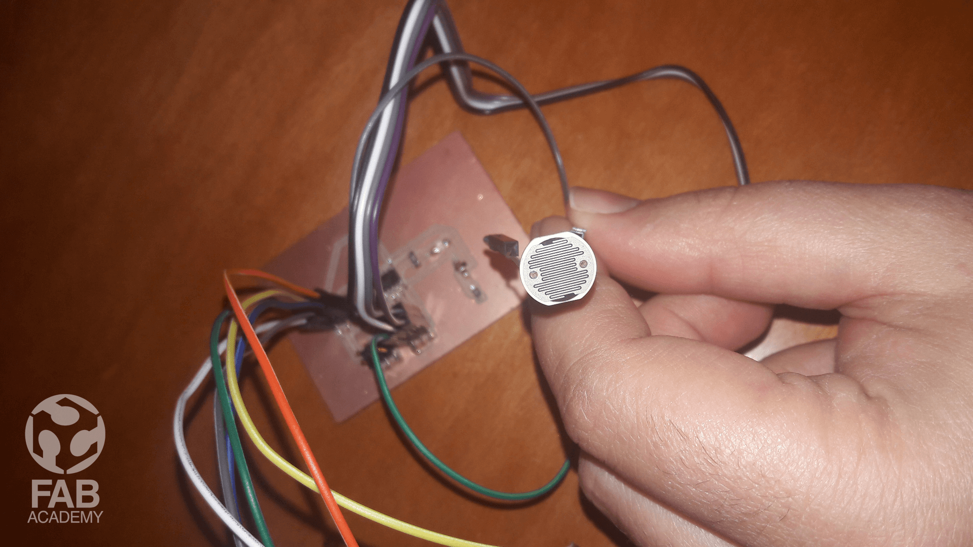
Then, After I was done with designing and milling the board I started soldering all the components .
As usual I started with the most difficult part to solder and then I moved to the easiest one.
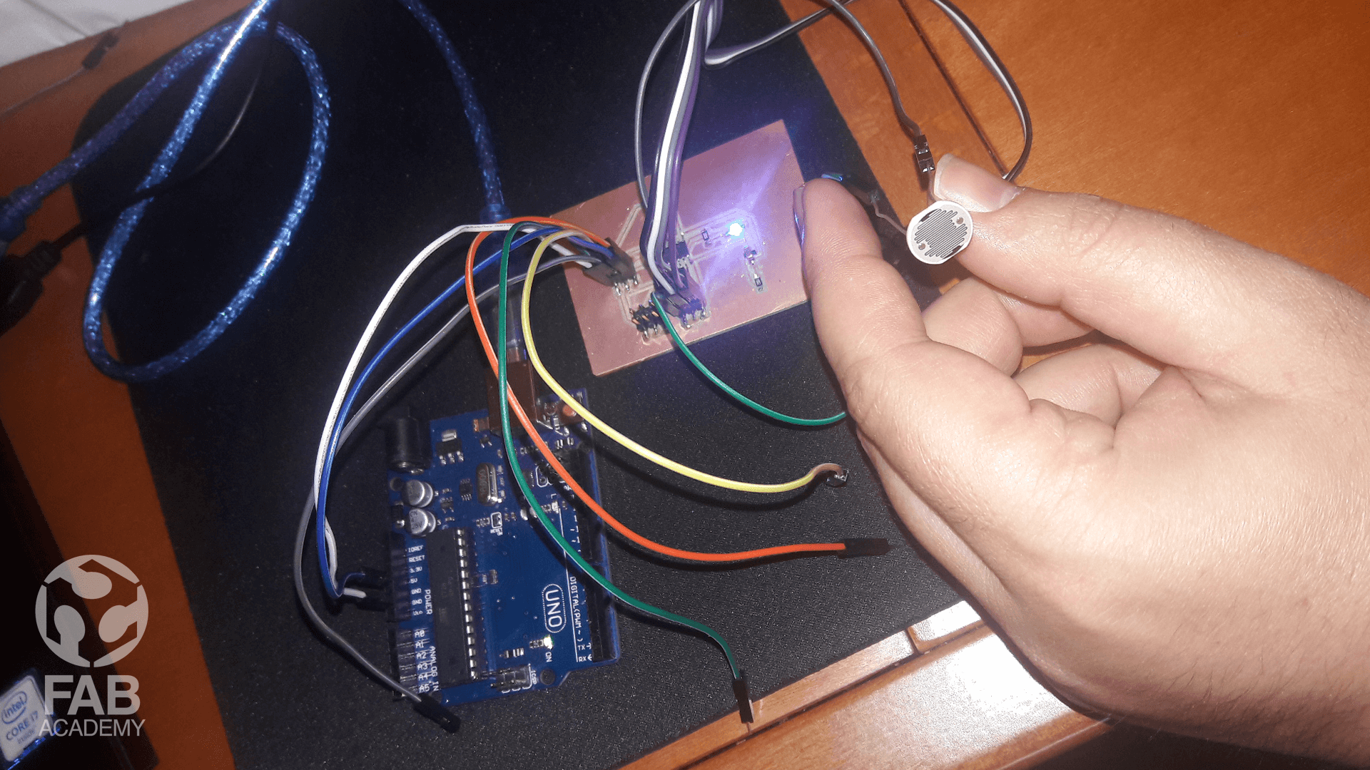
Next, I wanted to use Arduino as my ISP so connected my board to Arduino Uno as shown in image #
Then I uploaded the below code on my board and everything worked super fine.
Frankly speaking I did not have any problem in programing this board at this stage since it was based on the initial Attiny 85
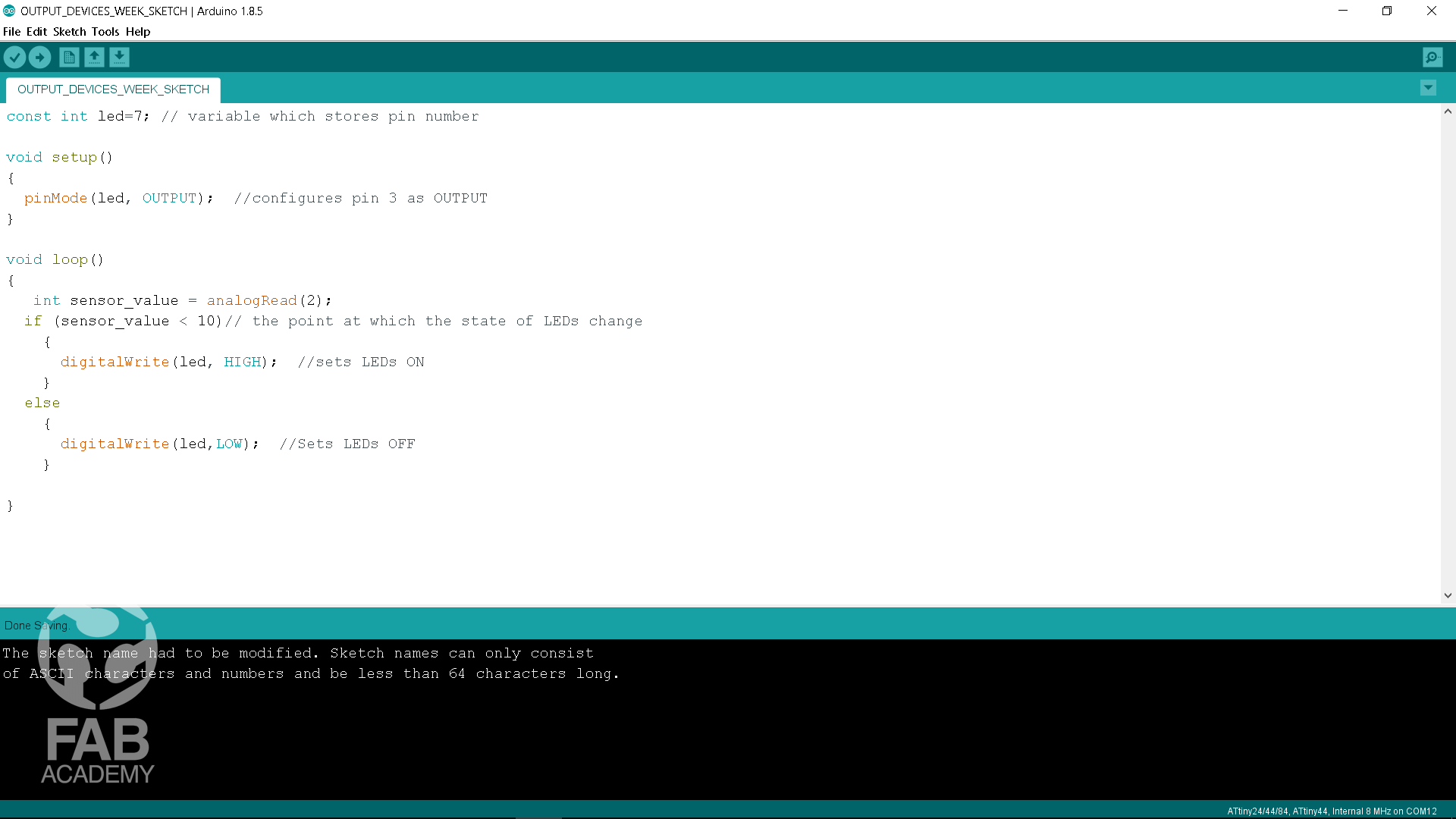
Below is the code that I have uploaded :
/*
This code was modified by Georges Hanna Fab Academy 2018, OUTPUT DEVICES

The code was modified Based on the below code :
https://www.digikey.ca/en/maker
/projects/08a1813ffe6d43b0899f29d08f350547

*/


const int led=7; // variable which stores pin number
void setup()
{
pinMode(led, OUTPUT); //configures pin 3 as OUTPUT
}
void loop()
{
int sensor_value = analogRead(2);
if (sensor_value < 10)// the point at which the state of LEDs change
{
digitalWrite(led, HIGH); //sets LEDs ON
}
else
{
digitalWrite(led,LOW); //Sets LEDs OFF
}
}
DOWNLOAD SECTION
+ OUTPUT WEEK BOARD DESIGN.sch DOWNLOAD .
+ OUTPUT WEEK BOARD DESIGN.brd DOWNLOAD .
+ W12_OUTPUT_DEVICES.ino DOWNLOAD .